

Howdy, Stranger!
It looks like you're new here. If you want to get involved, click one of these buttons!
Categories
- 247.5K All Categories
- 22 >> Start Here <<
- 12 New Members
- 8 FAQs
- 88.7K Gear
- 40.4K Guitar
- 3.5K Acoustics
- 1.3K Bass
- 15K Amps
- 17.6K FX
- 347 Digital & Modelling
- 784 Other Instruments
- 8.4K Making & Modding
- 428 Gear Reviews
- 107 Guitar Reviews
- 74 Amp Reviews
- 119 FX Reviews
- 88 Other Reviews
- 756 Made in the UK
- 985 Theory
- 1.9K Technique
- 2.2K Live
- 3.2K Studio & Recording
- 2.2K Making Music
- 230 Events
- 15 Guitar Show 2018
- 864 Plug My Stuff
- 107.9K Classifieds
- 42.2K Guitars £
- 2.9K Acoustics £
- 145 LH Guitars £
- 922 Basses £
- 10.9K Parts £
- 18.8K Amps £
- 34.9K FX £
- 2.9K Studio & Rec £
- 6.3K Misc £
- 469 Personnel
- 56.1K Chat
- 37.4K Off Topic
- 1.2K Tributes
- 6.7K Music
In this Discussion
Become a Subscriber!
Subscribe to our Patreon, and get image uploads with no ads on the site!
Pickup Winder for Mini Lathe
 Nomad
Frets: 549
Nomad
Frets: 549
Thanks to some impetus from @mrchi's thread about making pickups, I have started making a pickup winder of my own that has been at the back of my mind for a little while. It so happens that I occasionally cut up bits of metal and plastic for fun, which means I have a small metalworking lathe with electronic speed control. So, rather than make all the bits with the motor, bearings and speed control stuff, my plan is to make some attachments for the lathe.
I should mention that I'm not working to measurements or drawings with this (so far, at least). I'm basically designing it on the machine as I go, and using bits of metal that look about right.
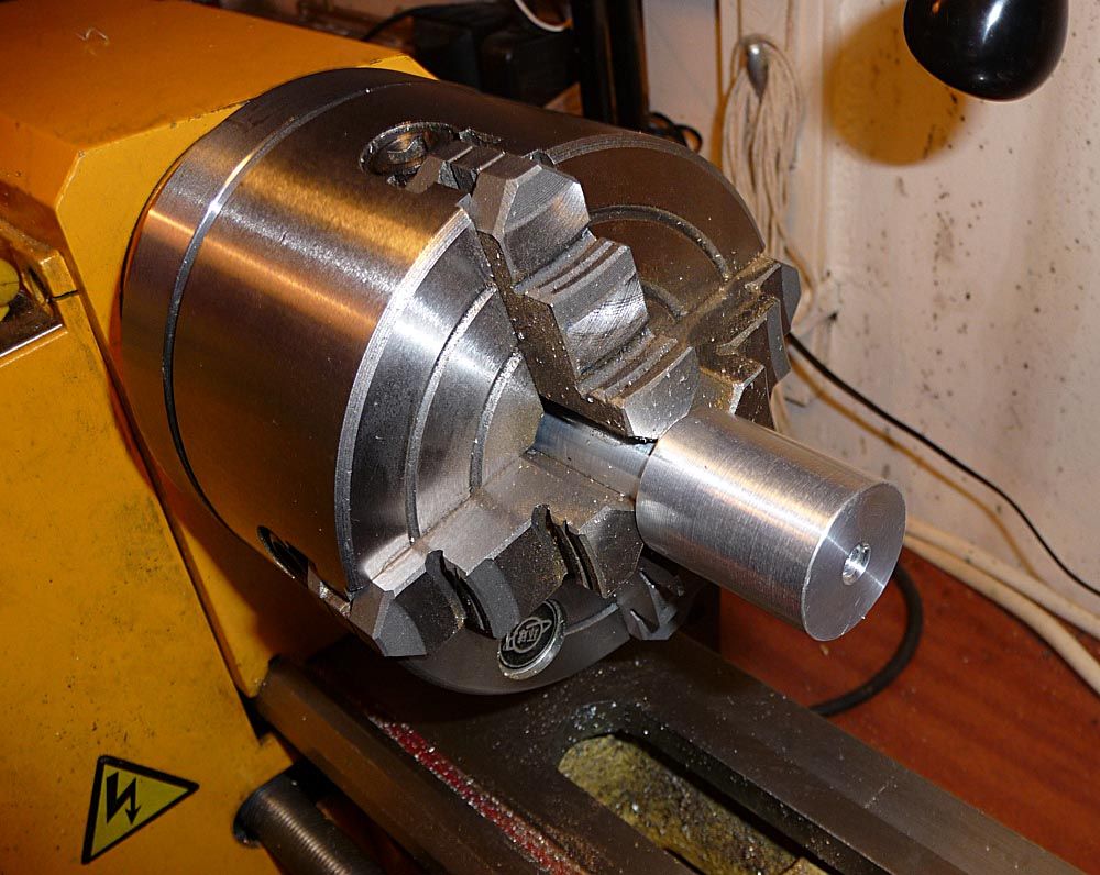
Here's the spinny bit...
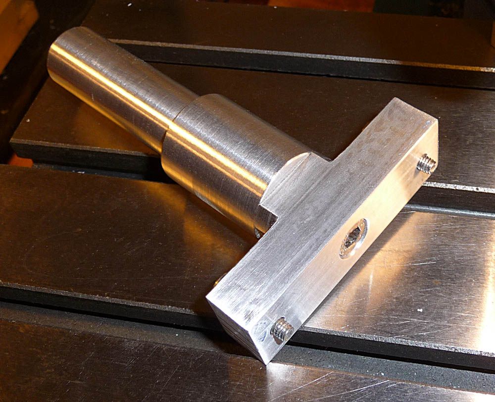
The spinny bit consists of two parts - a round thing and an oblong thing. The round thing gets clamped into the lathe chuck and has the oblong thing fixed to the end. The pickup components will be fixed to the oblong thing when the actual winding stuff happens.
The round thing is a lump of aluminium...
Note that it has a step - the diameter of the part inside the chuck jaws is smaller than the diameter of the bit outside. This is so that, when its fitted, the end will always be in the same place. This will make setup easier in the future (this isn't a conversion of the lathe - it's an attachment that will be fitted when it's needed, and removed when it isn't).
The reason there's a clear length of shaft sticking out of the chuck is to provide room for a dial test indicator (surface wobbliness detector thing). This chuck is not self-centring, so the part has to be dialled in to get it centred.
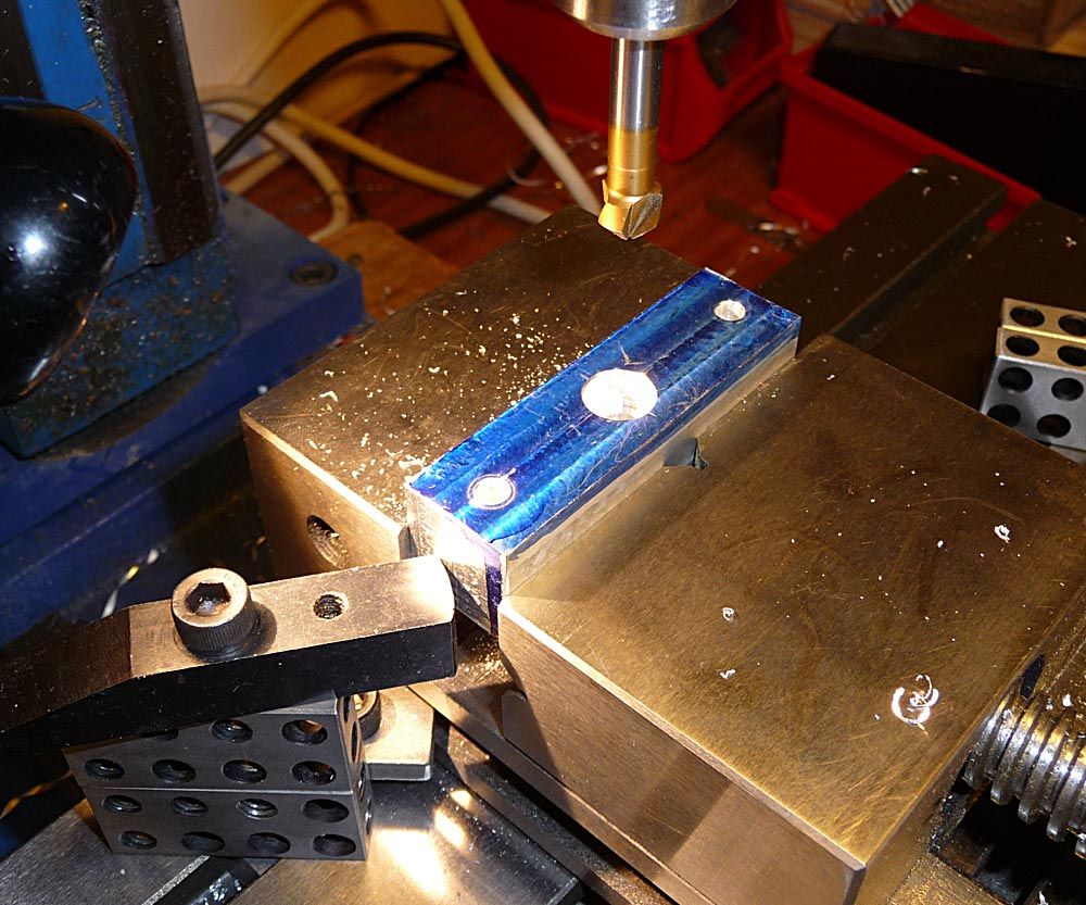
The hole up the middle is M6 and is for the fixing screw for the oblong thing, which can be seen here in the milling vice...
The hole in the middle is a counterbore - 6mm diameter through, and a 10mm diameter flat-bottomed hole on top of that, deep enough for an M6 capscrew. The other two holes are 4mm diameter for M4 fixing screws to be used for holding the pickup components.
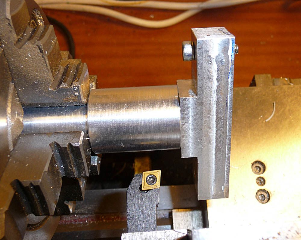
By the time I had found a couple of screws, I realised this bit of metal was a bit thick, so I flipped it over and cut a couple of rebates into it. I then fixed it to the round thing (still in the lathe) and rounded off the corners...
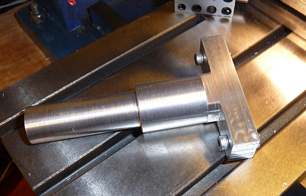
Here's the nearly finished spinny bit...
The ends of the M4 screws stick out about 3.5mm. The idea is that the pickup components will be mounted to an adapter plate, and that plate will then be fitted to the spinny bit. This way, I can mount the pickup flatwork using screws that come through the adapter plate from underneath, and then unscrew them from underneath when the pickup is wound. If I had the flatwork fixings coming in from the top, I'd have to make sure they were removable after the pickup has been wound.
There is one further part of this to be done - a mounting for the magnet that comes with the turns counter. That hasn't arrived yet, so I have no idea what size anything will be. I'll work that out when I get my hands on it.
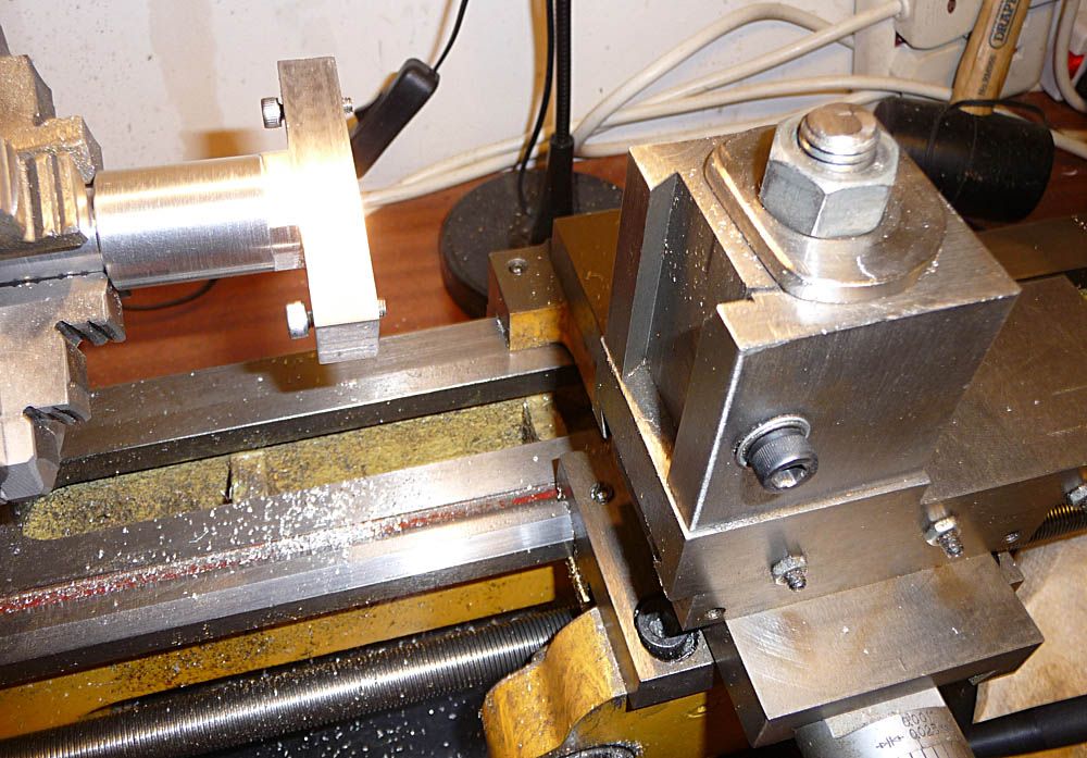
Meanwhile, I'll have a think about the static bit, which will hold the wire guide, the detector for the counter, and maybe a tensioner. This assembly will be mounted to the lathe's carriage...
The carriage is the lump of gubbins on the right-hand side. It moves left/right using a crank handle and can be locked in position. Near its left-hand edge, low down, there are a couple of M6 grub screws which can be removed to provide a mounting for something or other. The toolpost is the big square lump of metal with the dovetail slot in it, and could be used for mounting stuff as well, but its much more adjustable, and may make it harder to get a consistent setup.
Nomad
Nobody loves me but my mother... and she could be jivin' too...
 LOL 1
LOL 1 Wow! 0
 Wisdom
 Base theme by DesignModo & ported to Powered by Vanilla by Chris Ireland, modified by the "theFB" team.
Comments
The turns counter arrived a little while ago, and seems to work fine. Got it on eBay for 7 quid delivered. Also got some metal in the shape I needed for a couple of parts (5/8" square aluminium bar).
Been cutting up more metal today - mostly did some of the static part that fixes onto the carriage of the lathe (see earlier post). This consists of a flat bar arranged front to back, and two vertical bits. One vertical bit will hold a rod and a couple of collars for the wire guide, and the other is for the sensor and readout of the turns counter.
You can see how it's mounted here...
http://i1279.photobucket.com/albums/y521/Nomad_Zamani/Pickup%20Winder/PU%20Winder%20-%20Static%20Bit%2001_zpspyx5kxxv.jpg
Two M6 countersunk screws go down through the bar into the matching holes in the lathe carriage (after removing the grub screws that are normally there to keep swarf out). The vertical bits are held on with two more M6 screws coming up from underneath with the countersinks on the underside of the bar.
I also made a round recess in one end of the spinny bit to help retain the 12mm diameter magnet for the sensor, and made a little L-bracket to hold it in place.
Still to do are the rod and collars for the wire guide, and come up with some idea for the adapter plate that holds the flatwork.
I gave it a spin to check the speed. It does 1000 turns in about 50 seconds, or 1200rpm - a bit faster than the 1100rpm the lathe is supposed to do at the lower gear.setting.
Methinks I need to order some flatwork...
Nomad
Nobody loves me but my mother... and she could be jivin' too...
Formerly TheGuitarWeasel ... Oil City Pickups ... Oil City Blog 7 String.org profile and message
I'm planning to buy some ready made bits for now, but would like to make from scratch (especially for the lap steel - 8-string). I have access to a CNC milling machine at work, so I might give that a try if I can remember how to program it. Another possibility is using a 3D printer (which we might be getting), but I'm not sure if ABS is up to it - should be okay mechanically, but not sure about it withstanding the heat from soldering.
Is the plain fibre sheet available in the UK?
Nomad
Nobody loves me but my mother... and she could be jivin' too...
Formerly TheGuitarWeasel ... Oil City Pickups ... Oil City Blog 7 String.org profile and message
Got a question about the reel of wire, for anyone that cares to comment...
Is it better to draw the wire off the end of the reel (such as standing it up vertically and having the wire coming away upwards)? Or is it okay to have the reel horizontal on some sort of axle? The reel I have is quite heavy at 500g, and I'm a little concerned that the wire could break. I can rig up something with collars and bearings to make it run smooth and true, but it's still a hefty mass to start spinning while trying to control the tension of the wire. Also a bit concerned that the reel would keep spinning once I stop the winder.
Nomad
Nobody loves me but my mother... and she could be jivin' too...
Instagram
Formerly TheGuitarWeasel ... Oil City Pickups ... Oil City Blog 7 String.org profile and message
Thanks chaps - I'll work something out for feeding off the end of the reel.
Meanwhile, here's the next bit - the wire guide...
http://i1279.photobucket.com/albums/y521/Nomad_Zamani/Pickup%20Winder/PU%20Winder%20-%20Static%20Bit%2002_zps37c3zcmg.jpg
It's a bit of brass rod and two plastic collars. The rod is threaded M6 at the right-hand end, screwed into the square post, and a lock nut fitted to the far side. It may be noted that the rod extends out to the left much further than it needs to - the right-hand face of the left-hand collar could be moved much further left than the left-most inner face in a pickup bobbin fixed to the spinny bit. This apparent anomaly, however, is temporary and comes about from the design of the collars.
I wanted to avoid the screws in the collars marring the brass rod in the area where the wire is likely pass over in case a sharp bit developed that could damage the wire or its insulation. So, I put the screws at the outer edges of longish collars, which means that, for a given range of position adjustment, the screws will never contact the rod in an area that could be exposed to the wire. The collars are 25mm diameter and 25mm long, and the little thumb screws are M4, centred 4mm from the end. That means there is 19mm of smooth plastic inside each collar before we get to the screw, which means the range of size adjustment is 2x19 = 38mm. Should be more than enough for any range of pickup heights that I'm likely to encounter. The actual max gap available is 55mm.
The issue with the rod sticking out to the left comes about due to the length of the bracket that supports the sensor for the turns counter because the sensor has to align with the magnet on the spinny bit. The solution is to replace the bracket with a longer one. To get the sensor to line up again, I move the whole lathe carriage with the static winder bits to the right, and this will bring the wire guide to the right along with it. I won't know the new bracket length until I've decided how to do the adapter plate - the thickness of that influences where the left-hand collar needs to be, and I want that collar to be close to the end of the rod to maximise the amount of adjustment on the right-hand side.
Nomad
Nobody loves me but my mother... and she could be jivin' too...
Been thinking about how to hold the pickup in place during winding, and have elected to go for a combination of the magnets sticking to a bit of steel (the adapter plate, which hasn't been made yet), maybe with some dowels to get it lined up when putting it together, and a little plate pressing on the top of the pickup to help hold it on. Thus, the plate is a holder-onner.
Since I'm doing this on a lathe, the holder-onner plate is pretty easy to implement because I can use the lathe's tailstock to do the holding thing by fitting a rotating centre (a pointy, spinny thing that's used for some lathe jobs). The rotating centre has a cone bit that spins, and this is 60° (unlike a countersink cutter, which is 90°).
Here's the holder-onner in the vice, about to have the hole cut that the rotating centre will mate with...
http://i1279.photobucket.com/albums/y521/Nomad_Zamani/Pickup%20Winder/PU%20Winder%20-%20Holder-Onner%2001_zpsazsptg3n.jpg
The cutter in the chuck is called a centre drill. It has a short vertical portion, with an angled part just above. This angled part cuts the countersink shape, but has the 60° angle that matches the cone of the rotating centre.
Here it is after drilling...
http://i1279.photobucket.com/albums/y521/Nomad_Zamani/Pickup%20Winder/PU%20Winder%20-%20Holder-Onner%2002_zpsamhp5a3a.jpg
You can just about see the shape of the countersunk part of the hole, and the tip of the rotating centre is to the right. The hole doesn't go all the way through - needed to keep the countersink fairly shallow because I don't want the tip of cone to protrude through the other side.
Next, I used the bit of metal as a template to cut out a piece of rubber sheet and glued the two together...
http://i1279.photobucket.com/albums/y521/Nomad_Zamani/Pickup%20Winder/PU%20Winder%20-%20Holder-Onner%2003_zpsil8mnmjw.jpg
Bostik leather glue as it happens. Smear it on, leave until tacky, and then clamp lightly in a vice for a few minutes before trimming off the excess glue. The rubber acts as a mechanical buffer between the holder-onner plate and the top of the pickup. The idea isn't to clamp it all up so tight that the rubber compresses noticeably - just light enough to keep the pickup in place and to absorb any slight irregularities in the surfaces it contacts (magnet tops for a single coil pickup).
Here it is in place, mocked up with a random of bit of steel bar...
http://i1279.photobucket.com/albums/y521/Nomad_Zamani/Pickup%20Winder/PU%20Winder%20-%20Holder-Onner%2004_zpsamprtfeq.jpg
Seems to spin up okay (runs nicely centred and balanced), although I didn't run it very fast in case the lump of steel flew out. Here's a view from the other side, showing the tip of the rotating centre nicely mated with the hole in the plate...
http://i1279.photobucket.com/albums/y521/Nomad_Zamani/Pickup%20Winder/PU%20Winder%20-%20Holder-Onner%2005_zpslxgjvfqn.jpg
Nomad
Nobody loves me but my mother... and she could be jivin' too...
Studio: https://www.voltperoctave.com
Music: https://www.euclideancircuits.com
Me: https://www.jamesrichmond.com
Football is rubbish.
Made the adapter plate this evening. I had originally thought of something that had screws going through the plate into the bottom part of the pickup flatwork, and later considered using steel to take advantage of the magnets in the pickup assembly. However, when the flatwork arrived, I realised that it had some additional holes between the magnet holes. I was also rather pleased with the rubber-faced holder-onner, so I ended up making the bits in this photo...
http://i1279.photobucket.com/albums/y521/Nomad_Zamani/Pickup%20Winder/PU%20Winder%20-%20Adapter%20Plate%2001_zpsu7xczcn0.jpg
At the top is the pickup assembly, showing three additional holes between the six holes for the magnets (and the two holes at the ends for mounting in the guitar). Below that is the adapter plate itself. It has two M4 holes for fixing to the spinny bit, and an M6 hole in the middle. Next, there's a little bit of brass that is threaded M6 on the outside, and has a narrower bit that is a neat fit into the middle of the extra holes in the pickup assembly. Finally, there's a bit of rubber with a hole in the middle, and trimmed to fit the adapter plate.
The rubber gets glued to the plate, and the little brass thing (an alignment pin, essentially) gets screwed in from the back until the narrow part pokes through the rubber. This then gets fitted to the spinny bit, thus...
http://i1279.photobucket.com/albums/y521/Nomad_Zamani/Pickup%20Winder/PU%20Winder%20-%20Adapter%20Plate%2002_zpsoidq61kr.jpg
To use, the pickup assembly is presented to the adapter plate, middle hole over alignment pin, line it up roughly with the plate lengthwise, then bring the holder-onner onto the top of the pickup and nip up the tailstock to hold it all in place...
http://i1279.photobucket.com/albums/y521/Nomad_Zamani/Pickup%20Winder/PU%20Winder%20-%20Adapter%20Plate%2003_zpsyqjemspy.jpg
Using the alignment pin means that the pickup is immediately centred as soon as it's put in position. When the winding starts, this means that both ends will have the same wire tension. If it was off centre longitudinally, one end would be further from the centre than the other, which means it would be travelling faster, which would result in a stronger pull on the wire at that point and a corresponding weaker pull at the other end.
I'm pleased to report that this span up to full speed (1200rpm) no problem - smooth, balanced, and totally stable.
Going back to the positioning of the collars, I found that the reach of the tailstock is a limiting factor - it can only get so far left at max reach before it hits the carriage. The result is that there is still about 15mm or so of the brass rod sticking out to the side when the left-hand collar is in position. There is still enough adjustment on the right-hand collarto cope with any pickup height, so no need to mess around any more with that. This means that the final position of the carriage is set with respect to the spinny bit, so I can go ahead and make the revised bracket for holding the turns counter sensor in position. It did actually work in the current position, but it will get in the way if I have a pickup assembly that's any longer than this one (like an 8-pole one for a lap steel).
Nomad
Nobody loves me but my mother... and she could be jivin' too...
Been in the workshop again, and made a new bracket for the turns sensor...
http://i1279.photobucket.com/albums/y521/Nomad_Zamani/Pickup%20Winder/PU%20Winder%20-%20Sensor%20Bracket%2001_zpsrt1dszdu.jpg
It's a bit of aluminium with a 12mm wide slot at one end for the sensor, and a 4mm diameter hole at the other for mounting. The hole is above the centre line because I buggered up the height of the hole in the mounting post. Not that it matters. Here it is fitted...
http://i1279.photobucket.com/albums/y521/Nomad_Zamani/Pickup%20Winder/PU%20Winder%20-%20Sensor%20Bracket%2002_zpsscilxdt4.jpg
The slot is 20mm long (centre to centre), which gives me 10mm adjustment either way if I need to change the setup. There's also the option to drill another 4mm hole if that isn't enough.
With that in place, I was able to do a trial setup of the collars. At this point, the carriage is clamped in position, and the tailstock is slid as far left as it will go (until it bumps against the carriage), and the larger diameter of the spinny bit is against the jaws of the chuck.
Since I assembled the pickup parts using 0.5" wide spacers, it's easy enough to stick a bit of 0.5" wide thing in and bring the collars up against it...
http://i1279.photobucket.com/albums/y521/Nomad_Zamani/Pickup%20Winder/PU%20Winder%20-%20General%2001_zpsxt0bpxtl.jpg
The length of the pickup flatwork helps to keep it nicely aligned. With the collars in place, the bit of ally angle is removed...
http://i1279.photobucket.com/albums/y521/Nomad_Zamani/Pickup%20Winder/PU%20Winder%20-%20General%2002_zpspp83jvtz.jpg
Whether the spacing that results from this is 'correct', I can't say, but I think it's good enough to be going on with. If the wire snags on the edges of the flatwork, or doesn't get right up to the flatwork, I can try adjusting either the collars or my technique. I'll find out more about that when I try winding.
With everything positioned for a nominal setup to suit, in this case, a Tele neck pickup, there's one last bit to do - easy position repeatability of the carriage. As mentioned in an earlier post, the spinny bit has a narrow diameter that goes into the lathe chuck, and a large diameter that presses against the chuck jaws, which means that the reference surface that the flatwork is mounted on is always the same distance from the chuck. Something is needed to do the same thing with the carriage, and the hi-tech solution to this is a bit of stick cut to length...
http://i1279.photobucket.com/albums/y521/Nomad_Zamani/Pickup%20Winder/PU%20Winder%20-%20Carriage%20Spacer%2001_zpsw3cdfoqe.jpg
So, when I want to set things up, I put the spinny bit in against the jaws, and dial it in to centre it. Then put the bit of stick on the lathe bed and slide the carriage up against it before clamping in place. After that, the tailstock is slid up until it touches the side of the carriage, and that's clamped down. Fit rotating centre, fit pickup bits and holder-onner, and it's ready.
And that concludes the lathe-mounted parts of the winder. The last bit to do is the reel holder and something to de-flap the wire. For that, I'll need to pop out to B&Q...
Nomad
Nobody loves me but my mother... and she could be jivin' too...
...to get a couple of M8 threaded rods. The plan with these is to make a thing that clamps to the edge of the bench, with the wire de-flapper at the top and the reel somewhere near the floor. However, when I put it together, it felt a bit wobbly and it turned out that the rods were a bit too long. I couldn't be arsed hacksawing them and dressing the ends, so I decided to try the simpler method with the de-flapper at the top and just putting the reel on the floor.
Here's the de-flapper as it stands for now...
http://i1279.photobucket.com/albums/y521/Nomad_Zamani/Pickup%20Winder/PU%20Winder%20-%20Wire%20De-flapper%2001_zpsa0ecrp1y.jpg
A bit of plywood and a bit of bent copper brake pipe, held in by a couple of countersunk woodscrews from underneath. The bit of orange felt, in conjunction with a couple of MkI phalanges, is the tensioner.
I did a little trial wind of about 1600 turns, and it all seems to work. I think the tension needs to increase a bit. To all intents and purposes, however, it appears to be a working home-brew pickup winder.
Costs...
Turns counter: £7
Bought metal, pro-rata: £1 (max)
The rest of the bits I already had lying around. If I do use the threaded bar, I'll add £7.50 for that and some M8 wing nuts. So, under a tenner, or under 20 quid.
The lathe itself wasn't so cheap, of course (over half a grand), but it wasn't bought for this, and certainly isn't dedicated to it.
Nomad
Nobody loves me but my mother... and she could be jivin' too...
Here's a couple of shots of my test wind...
http://i1279.photobucket.com/albums/y521/Nomad_Zamani/Pickup%20Winder/Test%20Wind%20A%2001_zpsasno8tkp.jpg
http://i1279.photobucket.com/albums/y521/Nomad_Zamani/Pickup%20Winder/Test%20Wind%20A%2002_zpsprw9ufzl.jpg
There are some loose turns around the outside, but most of it feels okay. To be more exact, it feels solid at the ends, but in the middle, there is some give in the wires. I kinda expected that, although maybe not as much as there seems to be. Then again, with only 1600 turns, maybe it needs more before it feels solid all over.
To start it, I threaded the wire through the eyelet three times, and then trapped the loose end under the flatwork when I put it against the adapter plate. When I turned the lathe on, there was no slippage that I could see. From start-up, I had it going at around 500rpm almost right away, and then up to max after maybe 2-300 turns. During the early turns, it seemed as if the wire wasn't getting right up to the flatwork - I could see the wire building up, and a little gap of 1mm or so between the build-up and the flatwork. Had that at both sides. I concentrated a bit more on the sides and it seems to fill up (as can be seen in the photos). The wire would have been passing through the felt about 10" from the guide collars.
Nomad
Nobody loves me but my mother... and she could be jivin' too...
Decided to make the reel dangler, if only to see if it's better than having the reel on the floor. With the first full wind, I kind of had to keep the positions of my feet in mind in case I shifted and kicked the reel. In other words, I daren't move at all unless I was looking down. The reel dangler raises the reel up a bit from the floor, and the wooden base provides a guard in case a foot does move - then, the reel will only wobble a bit rather than have a minor disaster with a broken wire.
Here it is, hanging on the wall...
http://i1279.photobucket.com/albums/y521/Nomad_Zamani/Pickup%20Winder/PU%20Winder%20-%20Reel%20Dangler%2001_zpsr54dw2rl.jpg
Consists of the original top part with the bent brake pipe, two lengths of M8 threaded rod cut to length, and a rectangular base with a plastic rod in the middle for the reel to fit over.
Clamped to the bench...
http://i1279.photobucket.com/albums/y521/Nomad_Zamani/Pickup%20Winder/PU%20Winder%20-%20Reel%20Dangler%2002_zpsch2zcusr.jpg
There's an inch or so clearance underneath the base. I used nyloc nuts at the top, but wing nuts at the bottom in case I want to raise the base.
Reel in place...
http://i1279.photobucket.com/albums/y521/Nomad_Zamani/Pickup%20Winder/PU%20Winder%20-%20Reel%20Dangler%2003_zpsbjbclrfy.jpg
The top of the plastic rod has a big chamfer on it to help it through the top hole in the reel - the reel drops on with no snagging.
Nomad
Nobody loves me but my mother... and she could be jivin' too...