

Howdy, Stranger!
It looks like you're new here. If you want to get involved, click one of these buttons!
Categories
- 242.8K All Categories
- 22 >> Start Here <<
- 12 New Members
- 8 FAQs
- 87.1K Gear
- 39.7K Guitar
- 3.4K Acoustics
- 1.3K Bass
- 14.7K Amps
- 17.3K FX
- 284 Digital & Modelling
- 766 Other Instruments
- 8.3K Making & Modding
- 422 Gear Reviews
- 107 Guitar Reviews
- 73 Amp Reviews
- 119 FX Reviews
- 87 Other Reviews
- 750 Made in the UK
- 977 Theory
- 1.9K Technique
- 2.1K Live
- 3.2K Studio & Recording
- 2.1K Making Music
- 225 Events
- 15 Guitar Show 2018
- 839 Plug My Stuff
- 105.7K Classifieds
- 41.3K Guitars £
- 2.8K Acoustics £
- 141 LH Guitars £
- 903 Basses £
- 10.6K Parts £
- 18.4K Amps £
- 34.2K FX £
- 2.8K Studio & Rec £
- 6.1K Misc £
- 465 Personnel
- 55K Chat
- 36.7K Off Topic
- 1.1K Tributes
- 6.6K Music
In this Discussion
Become a Subscriber!
Subscribe to our Patreon, and get image uploads with no ads on the site!
MJW Amps -- New Build for Thorpy FX. BUILD PICS!
Base theme by DesignModo & ported to Powered by Vanilla by Chris Ireland, modified by the "theFB" team.
Comments
But they are more expensive to manufacture, hence why they aren't used as much.
Bear in mind transformers were my least favourite part of my A level so take it with a pinch of salt so feel free to correct me if I have gone wrong anywhere!
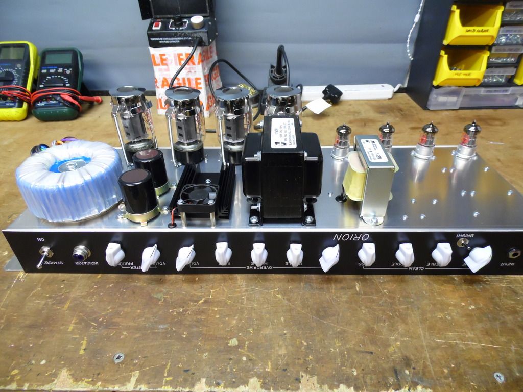
A pic of the completed chassis wiring:
The next stage is to finish the design and drawings for the turret boards and layout, and then get those built and fitted.
These are the turret boards for the amp, awaiting populating with components. I'm using 'perf' board on this one, as opposed to the blank board I use on some amps. I'm coming over to use this more these days, as although it costs a lot more, it save a fair bit of time drilling the plain board to a template.
The clean channel board is on the left, and the overdrive and power amp are on the right.
The boards are then populated and are shown here offered up on to their stand-offs. Also, you can see the relays for channel and boost switching, and the SDM Zero Loss loop PCB attached to check clearance.
The amp is working now and being tested, and the cabinet build is underway. Hoping to complete it for delivery early next week.")
You've clearly been a very good boy indeed!
Nearly finished now. I did some tweaking to the boost function, and have added a second relay to switch some additional functions to improve the sound in the unboosted mode. I'd hoped to do it with one DPDT relay, but tonally it wasn't up to my expectations. With 2 relays, the boosted mode is pure SLO, and unboosted is 2203/JCM800 in tone, and has better access to lower gain crunches.
On with the cab then. Here's a pic of the woodwork. High quality 18mm Baltic Birch ply, butt jointed, stapled and glued with Titebond. Well, it's enough to hold the neck on a Gibson! A very strong construction method, ask any Matamp owner.
Here's a snap of the parts required to complete the amp, including the footswitch and cable. Just noticed that I forgot to include the corners, ah well. Note the steel bar handles. The footswitch has now had the switches replaced with DPDT and LEDs added. It has a 5-pin DIN socket on the rear, meaning you can replace the cable more easily, or use different/shorter/longer ones.