

Howdy, Stranger!
It looks like you're new here. If you want to get involved, click one of these buttons!
Categories
- 241.4K All Categories
- 22 >> Start Here <<
- 12 New Members
- 8 FAQs
- 86.6K Gear
- 39.5K Guitar
- 3.4K Acoustics
- 1.3K Bass
- 14.6K Amps
- 17.2K FX
- 266 Digital & Modelling
- 765 Other Instruments
- 8.3K Making & Modding
- 420 Gear Reviews
- 107 Guitar Reviews
- 73 Amp Reviews
- 118 FX Reviews
- 87 Other Reviews
- 748 Made in the UK
- 972 Theory
- 1.8K Technique
- 2.1K Live
- 3.2K Studio & Recording
- 2.1K Making Music
- 218 Events
- 15 Guitar Show 2018
- 829 Plug My Stuff
- 105.1K Classifieds
- 41K Guitars £
- 2.8K Acoustics £
- 138 LH Guitars £
- 896 Basses £
- 10.5K Parts £
- 18.3K Amps £
- 34K FX £
- 2.8K Studio & Rec £
- 6.1K Misc £
- 465 Personnel
- 54.7K Chat
- 36.5K Off Topic
- 1.1K Tributes
- 6.6K Music
In this Discussion
Become a Subscriber!
Subscribe to our Patreon, and get image uploads with no ads on the site!
The community repair thread
So i know there's quite a few of us on here that repair stuff from amps to cars to house electrics and boilers etc. So I thought start a thread. Show a repair and list what it is, what's wrong with it and why, in your opinion it failed.
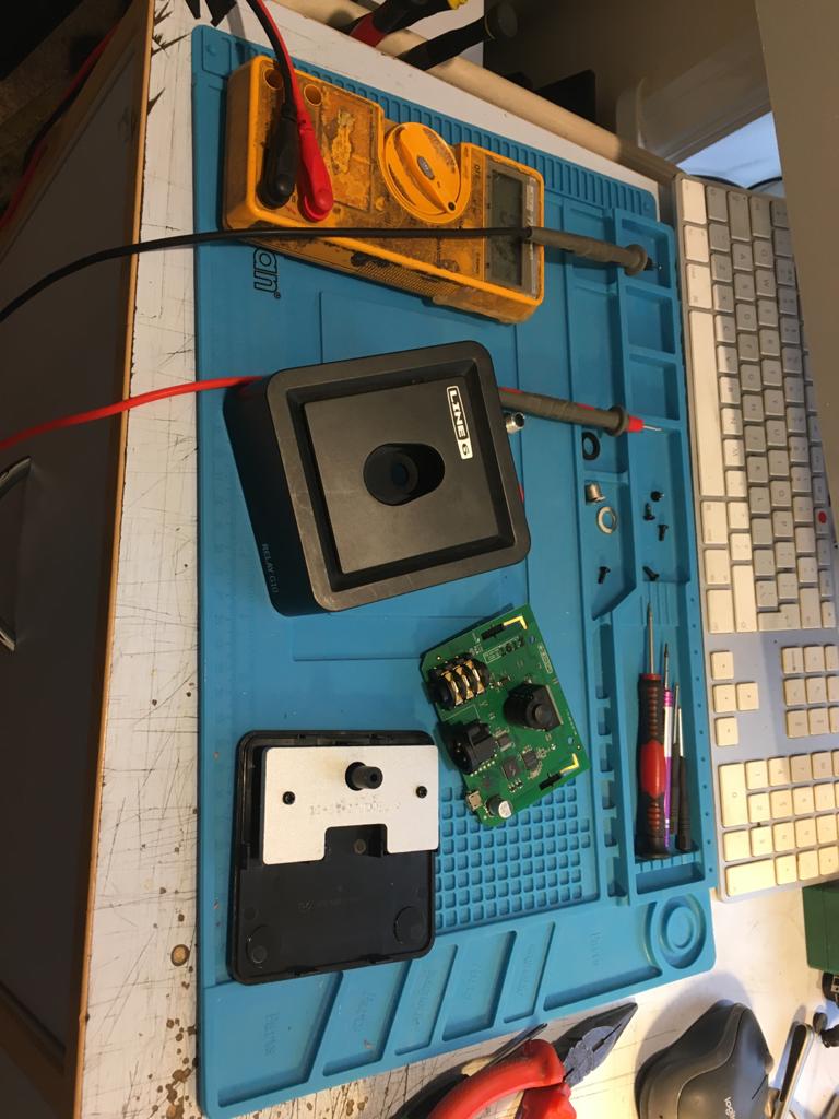
So here's the first from me. This is a Line 6 Relay G10 guitar receiver which also charges the transmitter. What a good idea and it really is except it's powered by a micro USB port connection. This is why it's on my bench, unsurprisingly it's broke.
So it's a line 6 Relay G10. It won't turn on because there's no power coming in via the micro USB port. Why has this failed ? ...well this port is literally the worse interface port ever ... it breaks in every day use on phones, tablets etc .... It was never designed to be used in this application. They could have used a standard 9V neg centre socket for the powering of the unit ... which I imagine would suit pedal boards better and still had the micro USB port for data .. like firmware update or whatever but they have deciding using this pathetic little port for everything.
Taking it apart is as simple as unscrew the nuts on the 2 jack sockets, unscrew the 2 screws on the XLR socket and there's one hidden screw on the bottom under a sticker. Once those are out use a pick to release the clips and then you can get the board out which has everything on it.
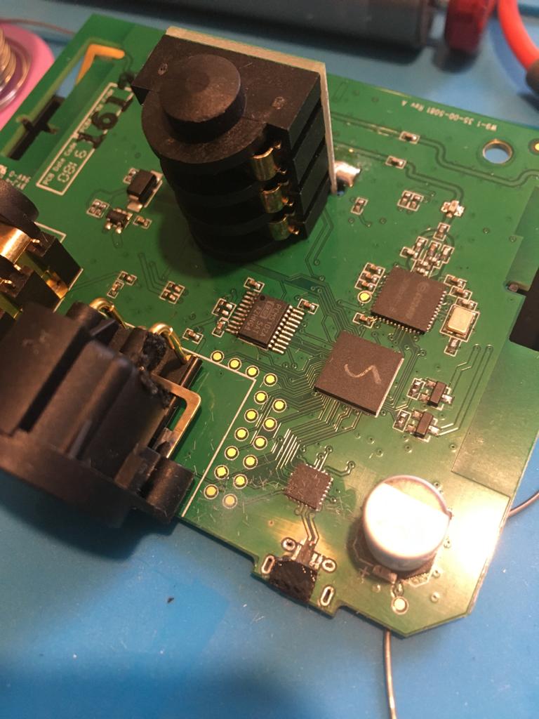
Now as often is the case I'm not the first one to get this repair and someone has tried to either resolder the micro USB port or tried to remove it ... whichever they have succeeded in shorting 3 out of the 5 pins together. They have used a lot of heat too ... on further inspection I can see the inner data pin traces have been vaporised so this isn't going to be a quick socket change. Oh joy !
Right so f#cked socket off, a clean up and i'm left with this. There's 5 pins on micro USB, we have VCC, ground and mode detect but the diff pair for data have been heated so much they aren't even there anymore. One tip here is if you don't have a good hot air gun cut away the socket until isn't possible to heat and remove each leg of the socket at a time. That way you won't destroy the pads. That horse has bolted here though so I need to somehow rebuild them. Now in case your wondering will it work without the data pins the answer is a little complicated. It will certainly have volts and ground BUT it needs the data pair for comms like firmware update and in some cases it needs to see 2 resistors connected to these pins to tell some chargers to commence. These resistors are the other side of the board. I don't have a schematic for this thing so I'm going to try and reconnect all five pads.
So first I cut a small piece of doubled sided tape, which in this pic is black. I use black because It's the same tape used in phone and tablet repairs but any double sided tape will do.
Now we cut 2 copper strand from the shield of a guitar cable (not a good cable ... just an offcut ) and lay them as a PCB trace pressed into the tape so keep them in position.

Then I solder quickly and cleaning to the good portion of the tracks after scraping some of the mask off to expose the copper. Now we have 5 pads again")
So the actual socket you need is this one ... it's the generic one used on Lenovo tabs and such
https://www.ebay.co.uk/itm/Micro-USB-Charging-Port-Charger-Connector-Socket-for-Lenovo-Tab-2-A10-70F-ZA00/163597003787?ssPageName=STRK:MEBIDX:IT&_trksid=p2057872.m2749.l2649
Here's our patient all back up and running till it breaks again ... which it will. If this was mine I would add another standard boss socket for 9V in and regulate that down to 5V wired straight on the board. So even if the USB port broke you could still be wireless for the gig.
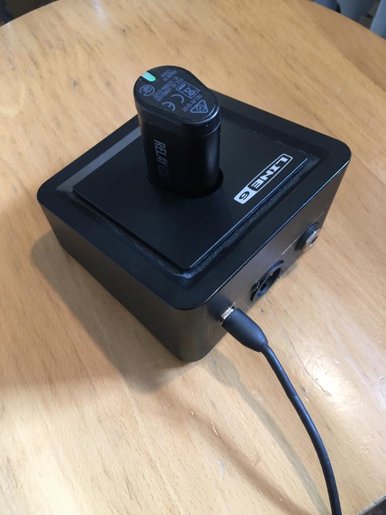
So that was one from me ... it's actually hard to remember to keep taking photo's as your doing this stuff .. plus the light needs to be reasonably good, I'll so better next time. In the meantime other to you. Could be a table leg you fixed, could be a fridge. I imagine there will be a lot of guitar related stuff but anything you repaired is valid
So here's the first from me. This is a Line 6 Relay G10 guitar receiver which also charges the transmitter. What a good idea and it really is except it's powered by a micro USB port connection. This is why it's on my bench, unsurprisingly it's broke.
So it's a line 6 Relay G10. It won't turn on because there's no power coming in via the micro USB port. Why has this failed ? ...well this port is literally the worse interface port ever ... it breaks in every day use on phones, tablets etc .... It was never designed to be used in this application. They could have used a standard 9V neg centre socket for the powering of the unit ... which I imagine would suit pedal boards better and still had the micro USB port for data .. like firmware update or whatever but they have deciding using this pathetic little port for everything.
Taking it apart is as simple as unscrew the nuts on the 2 jack sockets, unscrew the 2 screws on the XLR socket and there's one hidden screw on the bottom under a sticker. Once those are out use a pick to release the clips and then you can get the board out which has everything on it.
Now as often is the case I'm not the first one to get this repair and someone has tried to either resolder the micro USB port or tried to remove it ... whichever they have succeeded in shorting 3 out of the 5 pins together. They have used a lot of heat too ... on further inspection I can see the inner data pin traces have been vaporised so this isn't going to be a quick socket change. Oh joy !
Right so f#cked socket off, a clean up and i'm left with this. There's 5 pins on micro USB, we have VCC, ground and mode detect but the diff pair for data have been heated so much they aren't even there anymore. One tip here is if you don't have a good hot air gun cut away the socket until isn't possible to heat and remove each leg of the socket at a time. That way you won't destroy the pads. That horse has bolted here though so I need to somehow rebuild them. Now in case your wondering will it work without the data pins the answer is a little complicated. It will certainly have volts and ground BUT it needs the data pair for comms like firmware update and in some cases it needs to see 2 resistors connected to these pins to tell some chargers to commence. These resistors are the other side of the board. I don't have a schematic for this thing so I'm going to try and reconnect all five pads.
So first I cut a small piece of doubled sided tape, which in this pic is black. I use black because It's the same tape used in phone and tablet repairs but any double sided tape will do.
Now we cut 2 copper strand from the shield of a guitar cable (not a good cable ... just an offcut ) and lay them as a PCB trace pressed into the tape so keep them in position.
Then I solder quickly and cleaning to the good portion of the tracks after scraping some of the mask off to expose the copper. Now we have 5 pads again
So the actual socket you need is this one ... it's the generic one used on Lenovo tabs and such
https://www.ebay.co.uk/itm/Micro-USB-Charging-Port-Charger-Connector-Socket-for-Lenovo-Tab-2-A10-70F-ZA00/163597003787?ssPageName=STRK:MEBIDX:IT&_trksid=p2057872.m2749.l2649
Here's our patient all back up and running till it breaks again ... which it will. If this was mine I would add another standard boss socket for 9V in and regulate that down to 5V wired straight on the board. So even if the USB port broke you could still be wireless for the gig.
So that was one from me ... it's actually hard to remember to keep taking photo's as your doing this stuff .. plus the light needs to be reasonably good, I'll so better next time. In the meantime other to you. Could be a table leg you fixed, could be a fridge. I imagine there will be a lot of guitar related stuff but anything you repaired is valid
www.2020studios.co.uk
0 LOL 6
LOL 6 Wow! 5
 Wisdom
LOL 6 Wow! 5 Wisdom Base theme by DesignModo & ported to Powered by Vanilla by Chris Ireland, modified by the "theFB" team.
Comments
One simple idea that I have found really helpful over the years when dismantling & reassembling stuff like computers, even with a repair bench, is using a bit of cardboard as a template & screw holder (see photo for an example).
As the majority of screws are different diameters & lengths, this way you know precisely which one goes where. And if you drop it, the majority of screws will usually stay in place
When you do the inside of the machine, just draw rough outlines of the components like HD, battery, fans etc. onto another lump of card as landmarks & you're good to repeat the process.
And yes, the two small screws in the middle of this card, are from inside
Instagram
https://www.thefretboard.co.uk/discussion/73233/im-quite-pleased-with-this-bit-of-fixing
I had a similar problem with a cd player, but that backlight ran off 12V ac and adding a recifier was more trouble than it was worth.
Here's a useful trick for repairing a broken USB pen key that's got important files on it. This came in a couple of weeks ago. It belongs to a physiotherapist. She had it inserted in the PC, knocked it and completely f#cked it ! . Apparently it had years of important stuff on it (which kind of begs the question why are years of important stuff doing stored on a single pen key) but I declined to lecture her and took the job on. As it happens it was easy and fully do'able by you average person who can solder. This is how I got it
Obviously it's mangled so first job is get it apart. safest way is to cut all the plastic away, we are only interested in the data not repairing the pen key. So now I have this
As you can see the USB 3 connector has totally snapped off the PCB but it's quite a clean break and the tracks look good. Now as you can see there's 8 pads but I know i can get away with just using 4 which is 5V, ground and the the 2 data lines. So first thing to do is to connect wires to these 4 pads. Look at the pins on the connector and you can work out which pads are the ones you want. On this one it's pretty obvious but if it's not then the ground pin will be tied to common ground round the board. The 5V is the other end and the data lines are a differential pair so even the PCB tracks will be uniform. So wires on
Now i know that soldering isn't pretty but it doesn't need to be. Once the data's off the device is given back to the customer in bits with no wires and no clue to how I did it . Now you need to be absolutely sure you know you have the wires on the right pads, then you cut a USB cable so you have the USB type A connector with about 7 inches of cable. Bare the ends but keep them apart. Using continuity on a meter buzz through from the end connector to the bare ends so you can identify which colour cable is 5V which is Data + and so on. Don't trust the internet and any so called USB colour code .. there's loads of cables that use any colour they like. Buzz it through yourself so you know you're right. Then attach that to the wires you soldered to the PCB
Well that was it .... popped it in the mac and bingo, there's all her stuff. Once I sent her this photo she was One happy customer and I mean like very very happy indeed.
So once you have the USB drive working drag the lot onto your PC. Then copy onto a new USB drive but it's a good idea to keep the copy on the PC until the data has been safely backed up somewhere.
i haven’t got half a clue what that was all about, but I got immediately lost when you said there were “8 pads” when I am counting 9 silver bits ...
So if you need to repair a USB 3 penkey you can treat it as USB 2 and only need 4 from the 9 to copy data. I worked this out by working out how they made it backwards compatible
China but will probably get here before you need it
Thanks
On eBay, I often see very clean old cameras for pennies - described as not working even after a battery has been put in.
Most times, it’s because a battery has been left in and corroded the terminals.
The two key battery terminals are the ones inside - cotton buds with vinegar dissolve the battery oxidant and 99% isopropyl cleans it up a treat. Took 10 mins, popped a battery in and all working fine.
The fault that I see the most in things like that is the power supply won't turn on because the capacitors have failed. This is an inherent and common fault in any switch mode design. Often you can see the caps have failed because the tops will be bulging upwards rather than flat. This power supply is in an expensive Apogee audio interface, you can see the caps bulging, this is eventually what happens to an Electrolytic capacitor in a switch mode power supply. If the supply is well designed .. which this one is then turning on the unit will produce a light that will blink and go off as the PSU detects the abnormal load caused by the bad caps. If you see this on a TV or DVD recorder etc start by looking at the caps.
The rest of the power supply will generally be OK so as you say, it's worth doing.
I love the idea of using a cardboard/polystyrene template to hold dcrews - I'm never sure that I got the correct screw locations when reassembling my old HP laptop, although it never fell apart and it's still working albeit converted from Windows to Chrome OS.
I can't resist having a go at electronic repairs - a throwback to earning my living repairing TVs and later moving into IT. My old FM tuner in the hi-fi system started to fail after about 30 minutes use, Just out of warranty, obviously.
There was no way that this relatively expensive tuner was going to be scrapped, so out with a can of freezer and tracked it down to a small electrolytic capacitor. Fitted a replacement and the tuner is still working 20+ years later.
Laptop Repair. Here's a trick you can use for a dead laptop with no signs of any power.
Often a laptop won't turn on because no power is coming in to the board. First start with the charger. Check for 19V on the charger end. If you have that check the condition of the DC socket and more importantly is there 19V on any component near the socket ? To measure this use the chassis of a USB port as ground and then see if you can find 19V anywhere near the socket. If you can't and the socket isn't physically broke then chances are you have a direct short which is turning the charger off when it's plugged in.
If the laptop charger has a light, does it go out when you plug it into the board ? if it does then there's a direct short to ground on the board. If the charger doesn't have a light then hold it up to your ear and listen as you plug it in. If the frequency you can hear suddenly gets louder and normally higher then there's a direct short to ground on the board.
Now here's the clever bit. Fault finding a laptop motherboard is a painfully long task usually. It's very difficult to find the component that's causing the short because many other components will read shorted because they are on the same rail as the shorted component. However we can use heat to find the culprit. If we connect a form of power to the board that won't cut out when it detects a short, such as a few batteries in parallel for increased current the shorted component will heat up dramatically. Now you can use you fingers to see what's getting hot or cover the area in alcohol ... the thing that's shorting to ground will get hotter than anything else and the alcohol on it will dry instantly.
So here's an Acer motherboard with such a short. You can see I've found the short which was a bad capacitor and desoldered one end to remove the short to ground and the board powered up ok. Replace cap, job done.
One thing to be aware of when measuring laptop chargers is some use smart systems, Dell, HP, Lenovo etc and these chargers have 3 contacts. Outer sleeve is ground, inner sleeve is +19V and centre pin is SMART pin and normally 3 to 7 ish volts. This smart pin talks to the SMC to intelligently charge battery. So on these chargers make sure you measure the correct bit.
On dumb chargers like Asus, Acer, Toshiba etc it's just like a Boss power plug but centre pin is +19V, barrel is ground